From the archive: originally published 2013
DRSSTC 1
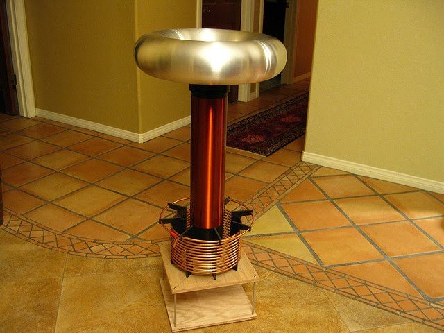
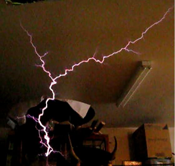
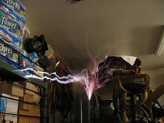
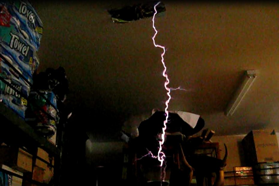
DRSSTC 1 was my first attempt at a DRSSTC type Tesla coil. It wasn't a super high performer, but it was still able to generate 4 foot sparks with 500 amps of current.
Recovered from the old goodchildengineering.com (Wayback Machine copy). Text as published in 2013; specs are as built then.
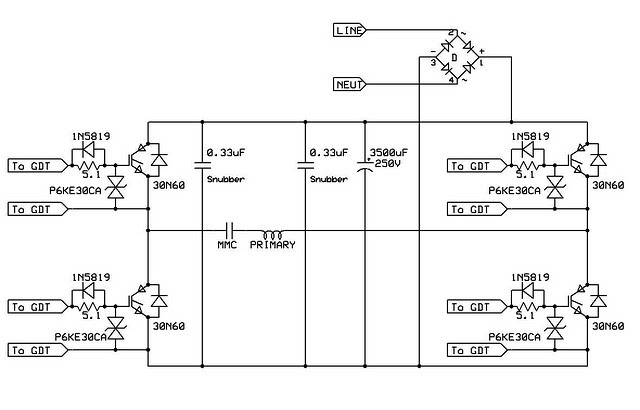
DRSSTC 1 was my first attempt at a DRSSTC type Tesla coil. It wasn’t a super high performer, but it was still able to generate 4 foot sparks with 500 amps of current. The coil’s high frequency inverter was designed using the IXYS 60N60 IGBT’s at the core, taking advantage of their pulsed-current capabilities. The IGBT’s were selected for this design because they operate with lower loses compared to MOSFET’s in pulse- current applications. IGBT’s operate like a diode with a fixed voltage drop, whereas MOSFET’s have an on-resistance. As a result, losses in IGBT’s go up linearly with current and MOSFET losses increase exponentially.
| Secondary | 4.5” x 18” winding of 32 AWG wire on ABS form |
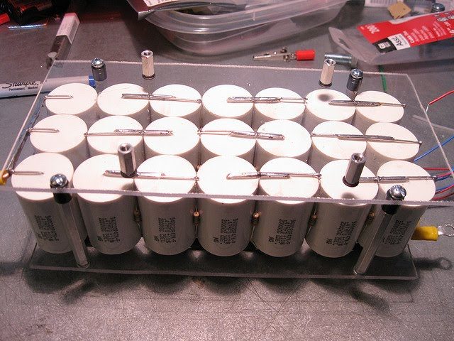
| Tank Capacitor | 0.2uF at 14KvDC made up of 0.47uF 2kv caps |
| Switch Type | Full Bridge of IXGN60N60C2D1 |
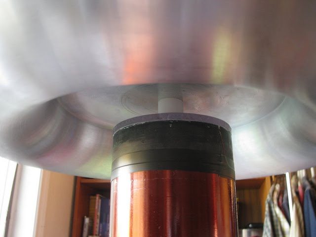
| Topload | 4.5” x 18” Spun aluminum toroid |
| Max Spark Length | 4 feet |
| Input Power | 120VAC 10A variac 1200VA |
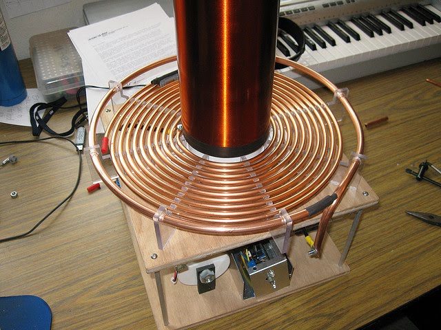
| Primary | 10 turns 1/4” copper tube flat primary tapped at 8.5 turns |
| Max bus voltage | 380VDC |
MMC
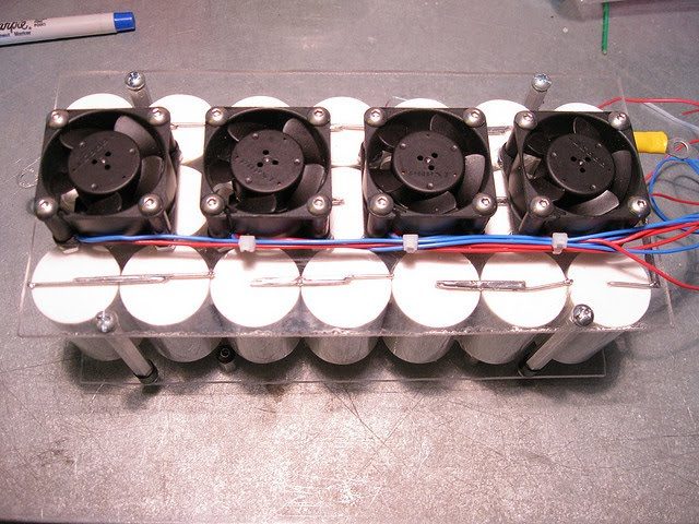
Because this is a resonant transformer, a high voltage capacitor had to be designed for use in the primary LC circuit. Rather than purchasing a commercially available pulse capacitor, I constructed the tank capacitor from many smaller capacitors. I connected the capacitors in series to achieve the correct voltage rating and paralleled strings to get the correct capacitance. The result is a capacitor known as a MMC or Multi Mini Capacitor. This type of capacitor is substantially more economical than a commercial pulse capacitor of the same value.
Power Electronics
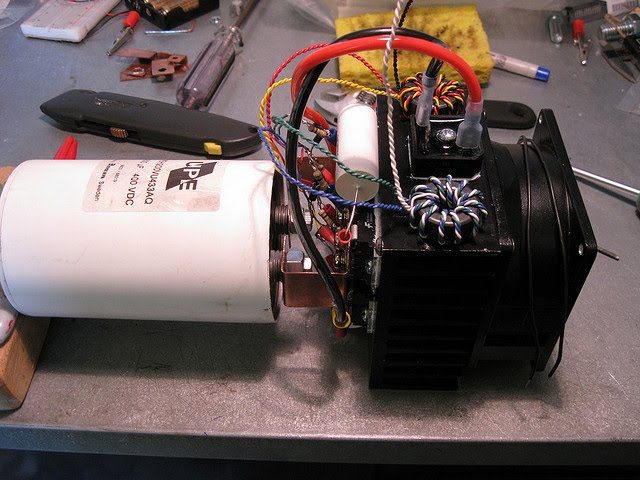
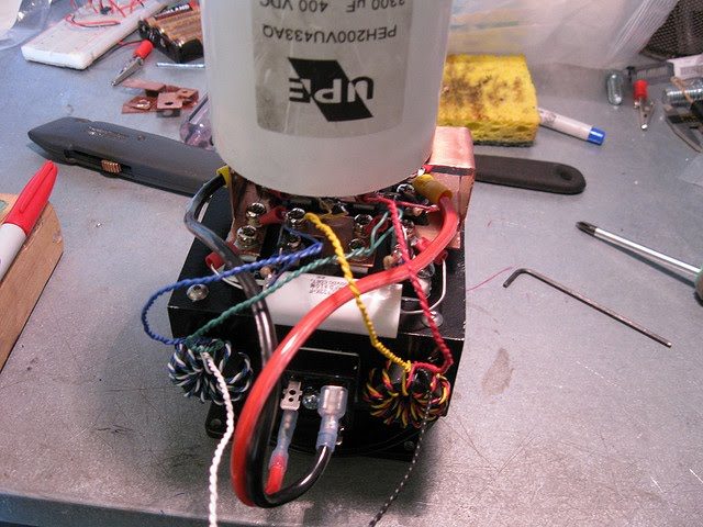
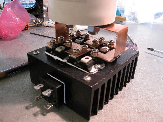
The primary LC circuit of the transformer was driven by an H bridge of the IXYS 60N60 IGBT’s running with a maximum of 380VDC on the bus. The bus voltage was obtained by full-wave rectifying 240VAC and filtering with a RIFA 3300uF 400VDC inverter grade DC link capacitor. The DC link capacitor also acts as a reservoir for the high-pulsed current needs of the IGBT inverter.
Secondary
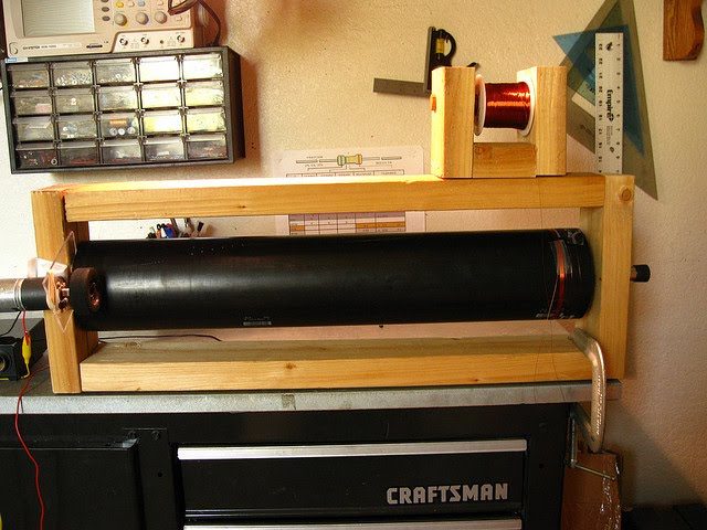
The secondary is an 18 x 4.5 inch winding of 32 AWG enameled copper wire, wound onto a 20 x 4.5 inch length of ABS pipe. At the top, a high voltage toroidal terminal was used for field control as well as added capacitance in the secondary LC circuit. A breakout point was also used to direct the high voltage in a particular direction and to give it a sharp point in which it could initially form.
Controller
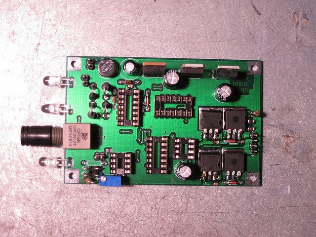
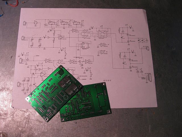
The board layout and schematic of the controller were both developed by Steve Ward, his driver page is here: Steve Ward Universal Driver
The version of the driver is the UD1.3b which is a basic, self-resonant controller with over-current detection circuitry and Zero Current Switching capability.
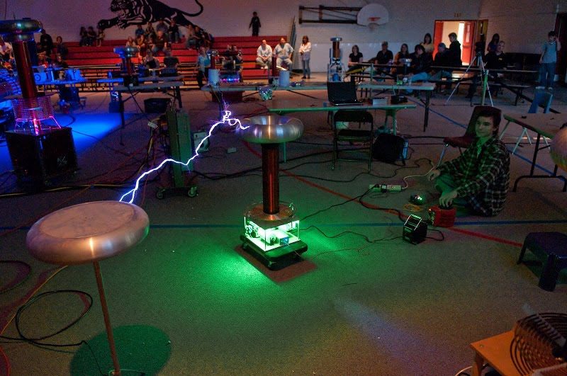
Some Sparks!
Later Upgrades
Some Improvement were later made to this coil, Including a flat primary and better toroid mounting.