From the archive: originally published 2013
DRSSTC 2
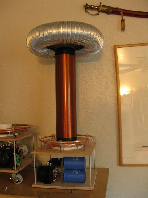
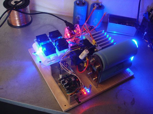
DRSSTC 2 started out as just another IXYS60N60C2DI coil and evolved into a platform for experimentation. As this project evolved it became one of my highest outputting coils for its size.
Recovered from the old goodchildengineering.com (Wayback Machine copy). Text as published in 2013; specs are as built then.
DRSSTC 2 started out as just another IXYS60N60C2DI coil and evolved into a platform for experimentation. Early development of this coil proved to be disappointing with less output than my original DRSSTC 1, but as this project evolved it became one of my highest outputting coils for its size.
Final Specs
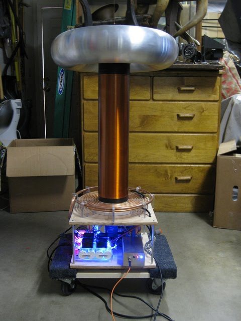
| Secondary | 4.5 x 18 inch winding of 30 AWG wire on ABS form |
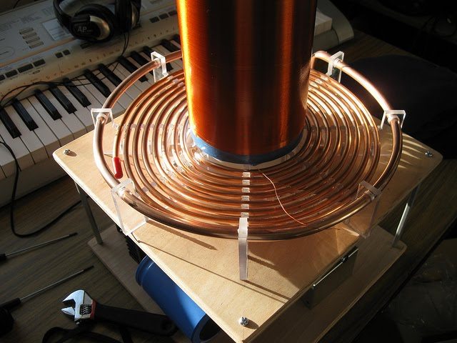
| Primary | 8 turns max 1/4 inch copper tube |
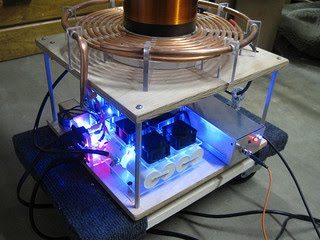
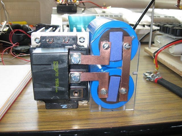
| Switch | CM300DU-24F (with RTC disabled) |
| Switch Configuration | Half Bridge With doubler |
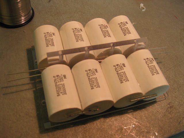
| Tank Capacitor | 0.2uF 8kv made up of 0.47uF 2kv CDE pulse caps |
| Topload | 4.5 x 18 Spun Aluminum toroid |
| System Fo | 120KHz |
| Controller | Steve Ward’s UD2.0 |
| Bus Voltage | 680VDC |
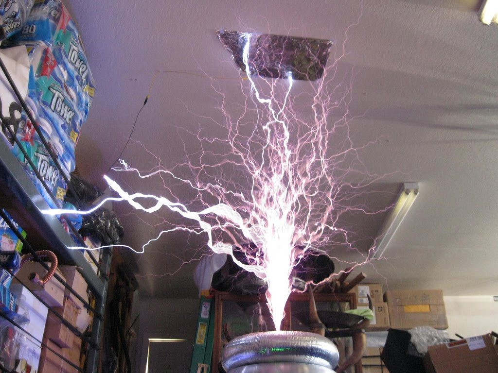
| Max spark length | 5.5 feet |
Early Beginnings…
In its early beginning this coil was very misbehaved. It killed 3 bridges of 60N60 IGBTs and didn’t have a whole lot of output to show for it. The original controller used was Steve Ward’s UD1.3b. The coil also didn’t start with a spun toroid, the original toroid was a 4 x 18 ducked tubing toroid which worked out but had a nasty habit of breaking out wherever it wanted. This coils secondary was also stolen from my early SSTC project.
MMC Design
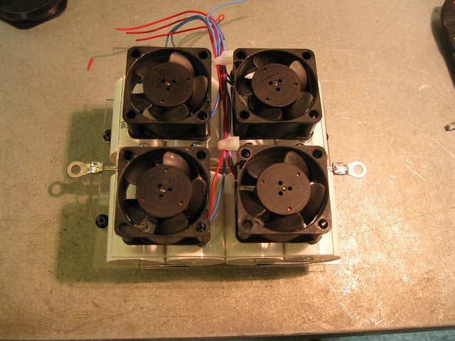
The original MMC was very undersized at only 8KvDC. It also got rather warm under operation due to it only having two strings of caps to handle all of the tank current which at time could be 700Apk+
Trying out Phase lead
At the time there was a lot of talk on 4hv.org and also on Tesla Universe about using phase lead with large IGBT brick in DRSSTC. I wanted to try out this new technique on my DRSSTC 2 because it was largely disappointing at the time and I would have no trouble ripping its guts out. The design that I decided to try was the UD2.0 developed by Steve Ward. I had used the early version of the UD board in my DRSSTC 1 and DRSSTC 2 and understood the workings of the board. Steve Ward graciously let me use his design and I quickly had some PCBs spun up.
The other thing I needed was a large and slow IGBT brick to run at a high Fo. At the time there were a bunch of CM300DU-24F IGBTs on eBay, so I snagged 4 of them for $25 each. Now the F series of CM IGBTs has a current limiting circuit (RTC) that had to be removed for DRSSTC use. It was a real chore digging arrowed in the sticky thermal gel that was in the IGBT to disable the RTC circuit. Detail on how to disable the RTC can be found on my old 4HV post.
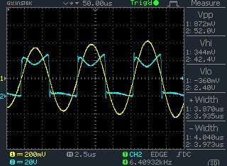
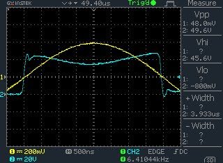
The way phase lead works is like this; in an optimal DRSSTC you want the IGBT to switch exactly when the current in the primary LC circuit crosses zero. With large brick type IGBTs this can be hard at higher Fo because of the IGBTs long rise and fall times. The solution is to start the switching of the IGBT early so that the IGBT has time to turn on or off before the zero crossing. The way this is done is by adding a variable inductor in series with the burden resistor on the feedback transformer. This way the feedback signal can be advanced by a set amount of time determined by the variable inductor.
The results with the new phase lead and CM300DU-24H were fantastic! I was able to achieve 5.5 feet from a stranded 120VAC 15 Amp outlet .