
From the archive: originally published 2013
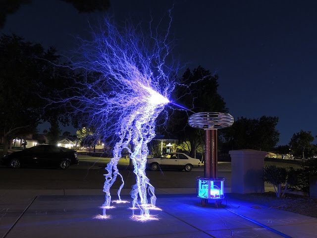
"Beast" The 15Kw 7' tall DR (DRSSTC 5)
The overall goal of this personal project was to build a big coil that made big sparks. It took over a year of work and a lot of testing and refinement to get this project to its finished state.
Recovered from the old goodchildengineering.com (Wayback Machine copy). Text as published in 2013; specs are as built then.


The overall goal of this personal project was to build a big coil that made big sparks. As simple as it may sound it took over a year of work and a lot of testing and refinement to get this project to it’s finished state.
Secondary
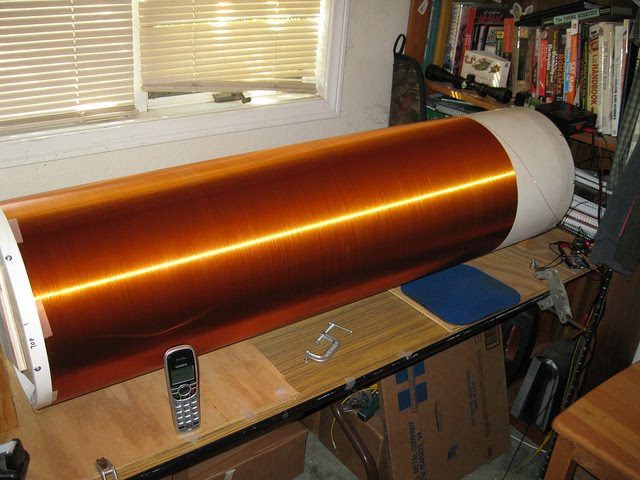
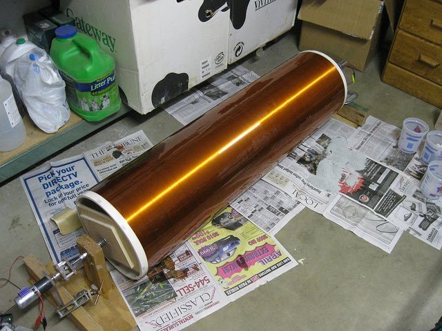
The secondary is the largest part of this coils, it’s also one of the most important. The secondary was wound on a 12.75 x 17 inch PVC form. 24AWG double build magnet wire was used, for the 45 inch winding. The winding was done on a custom built motorized winding jig. After the winding was complete the secondary was coated in two coats of polyurethane. After the form was sealed with poly, one thick coat of pour on epoxy was applied to the secondary. The secondary was then rotated for 8 hours at low RPM (5rmp typical) to allow the epoxy to harden. After 8 hours the secondary was taken off the jig and allowed 72 hours for a full cure of the epoxy.
Secondary end caps
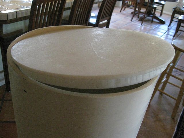
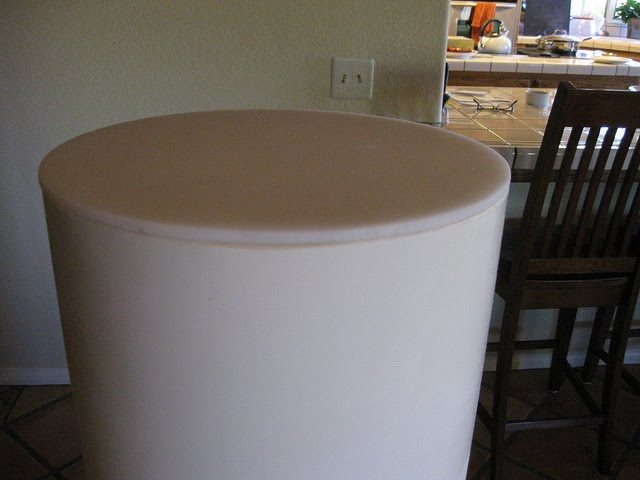
Another important part of the secondary are the end caps. The end caps have a couple of functions, they hold the toroid on the top of the secondary and they also hold the secondary down to the base of the Tesla coil. The end caps for this secondary were made from 12 x 12 inch 1 inch thick HDPE sheets. First two circles were cut from the 12 x 12 squares on a band saw. Then a notch was cut all the way around the outside of the circle, leaving a ¼ inch lip. These end caps are then presser fix into the end of the secondary and secured with nylon hardware. A ¾ inch threaded brass rod was used with the bottom cap to hold the secondary to the base and also act as a connection for RF ground. 5/16 threaded brass rod in conjunction with 4.5 inch PVC at the top to hold the toroid onto the top of the secondary.
Controller
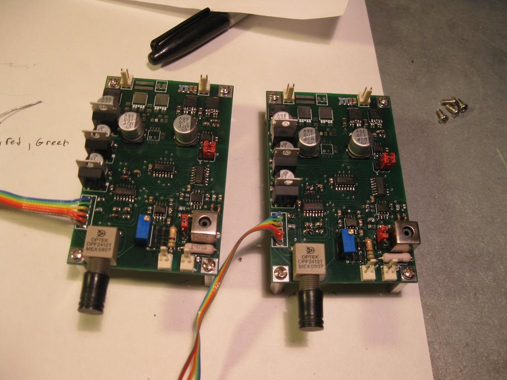
The Controller used is Steve Ward’s UD2.0; a DRSSTC takes advantage of what is known as soft switching. In order to soft switch IGBTs they must be turned on and off during the time that the sinusoidal current in the primary LC crosses zero. When using large brick type IGBTs this can be hard because of the large rise and fall times associated with large IGBTs. The solution to this problem is to use a technique call phase lead. With phase lead the burden resistor on the feedback current transformer is series with a variable inductor. With just a resistor the feedback voltage would be in phase with the primary current, but with an inductor in series the voltage now leads the current in primary by a preset value determined by the setting of the variable inductor. As a result the IGBT is turned on slightly before the zero crossing giving the IGBT time to turn on or off. This technique allows fast switching of the IGBTs with less switching loses. The UD2.0 was developed by Steve Ward, I take no credit in design of the controller or PCB layout. Steve Ward’s web site
Toroid
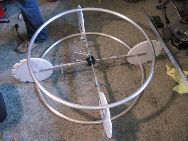
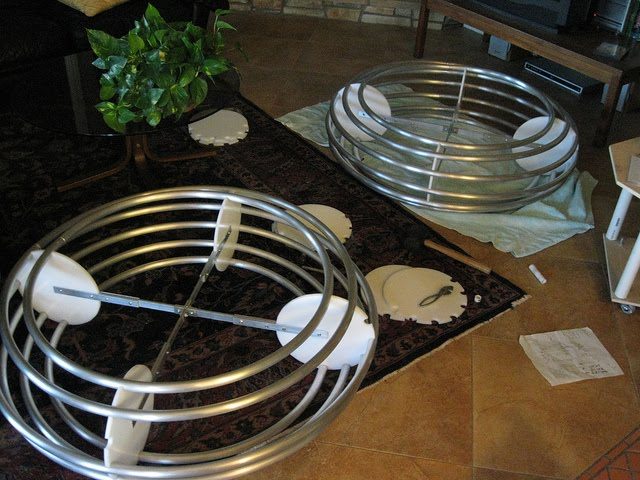
I didn’t want to use a duct tube toroid like many others have done on large coils. The trick was to build a toroid that looked good but didn’t cost a mint! So I designed a ring toroid which uses the combined surface area of 7 aluminum rings to get the correct amount of capacitance for the design. This design doesn’t look like a bunch of duct work that you would find in your attic!
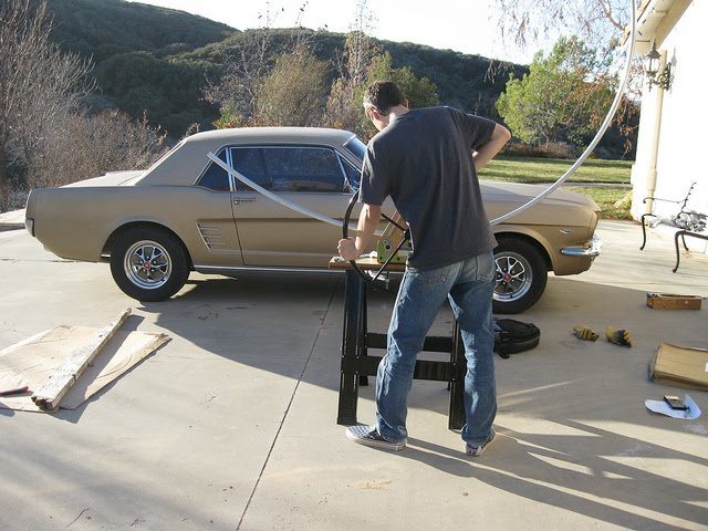
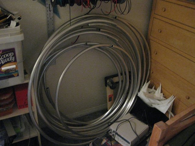
Construction of the toroids was also a fun task and was relatively simple. I started with the dimensions of the overall toroid, then worked out the diameter of all 7 rings on paper. Working out the circumference of the rings gave me the amount of aluminum pipe I needed to buy. I built the toroid during winter 2010 with T6 2024 1” OD 1/16 wall aluminum pipe, from a local metal warehouse, and the HDPE sheet from tapplastics.com.
I cut the HDPE in circles and added notches for each of the rings to snap into. I also purchased a tube bender from Harbor Freight tools to bend the pipe into rings. The pipe was bent at a slightly tighter circumference than the real ring, so that when a piece of PVC was inserted into the ends of the pipe the ring snapped together and held its shape.
The toroids took about 3 days to construct.
Primary and Base
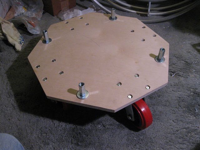
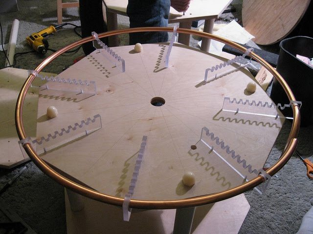
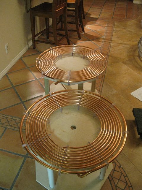
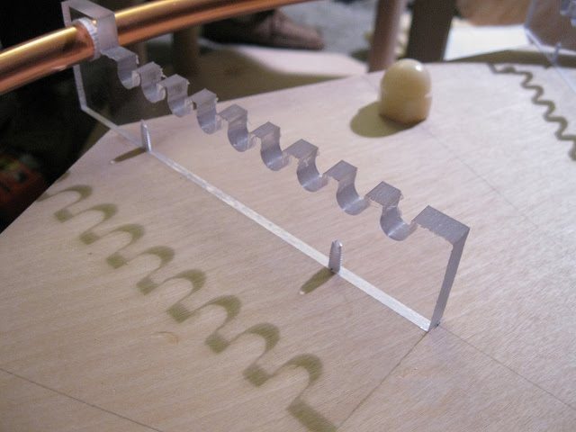
The primary and base assembly were also constructed during winter of 2010. The primary is made with 3/8” lexan sheet for the primary supports and 3/8” copper tube for the primary itself. During operation under peak current of <1KA, the primary is run air-cooled. But for primary currents >1.5KA, the primary can be water cooled. The casters for the base make it really easy for the coil to be push around. The primary spacing is 1/4” from the outside wall of each tube (not from center to center).
H bridge and MMC
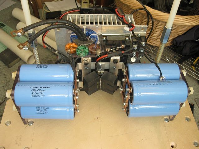
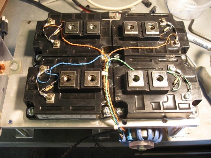
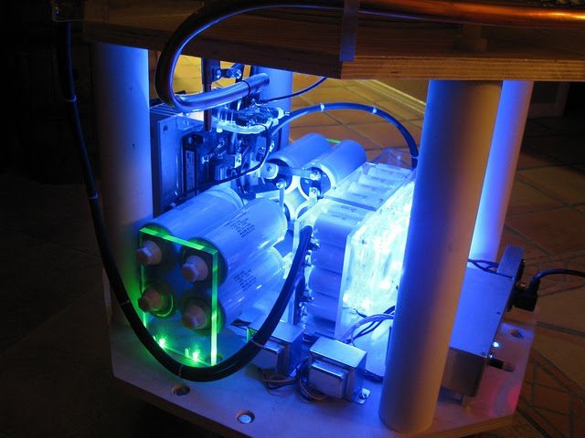
The H bridge and MMC are two of the most complex parts in this build, especially the H bridge. The bridge was constructed with CM600HA-24H IGBT’s and uses gate-drive transformer drive. Most gate drivers for bricks this size would never use GDT, but because this is a pulsed system which uses large, high-permeability cores for the GDT, this system is extremely simplified and reliable. The bridge is also the heaviest part in the base, topping out at a whopping 40 lb.
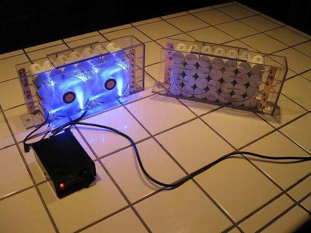
The MMC was relatively easy to construct and uses 7 caps in series to obtain the correct voltage rating and 4 strings of 7 caps to get the correct capacitance rating. The MMC is in a lexan-enclosed case with some fancy LED fans (the fans are really only for show). The wiring off the bridge and MMC is 2 AWG welding cable (two parallel cables).
Twin System and Faraday Suit
A Faraday suit was consturcted from chain mail that allows a person to get hit by the lightning. This suit has been very successful. The twin system is still being tested. We play music on the coils and do other fun stuff as well. This project will also continue to be updated well into the future.
Here is the system in action
Video: https://www.youtube.com/watch?v=uNJjnz-GdlE
Video: https://www.youtube.com/watch?v=bbLshnfu0wY
More videos can be found on our YouTube Channel More Photos can be found on our Flikr page