
From the archive: originally published 2013
2400W DRSSTC Twins
The overall goal of the twin DRSSTC project was to have a super reliable and portable system to take to demos. The systems were designed with MIDI demonstrations in mind.
Recovered from the old goodchildengineering.com (Wayback Machine copy). Text as published in 2013; specs are as built then.
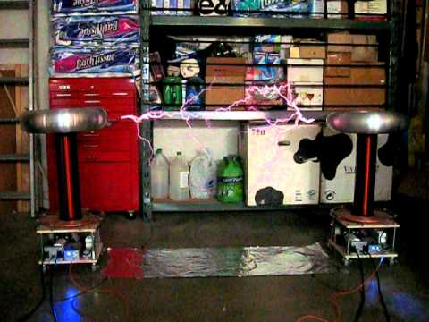

The overall goal of the twin DRSSTC project was to have a super reliable and portable system to take to demos. The systems was designed with MIDI demonstrations in mind and also to be able to run both coils off of a single 15A 120VAC breaker so there would be minimum hassle with power when demoing. These coils were developed with all the lessons learned from DRSSTC 1 and DRSSTC 2, most of the parts came from these two older coils.
Specs
| Secondary | 4.5 x 18 inch 32 AWG wire 1/16 epoxy coating |
| Primary | 10 turns max 1/4 inch copper tube flat |
| Tank Capacitor | 0.25uF 10Kv made up of 0.47uF 2Kv caps |
| Power Switch | CM300DY-12H |
| Switch Configuration | Full Bridge |
| Topload | 18 x 4.5 inch spun aluminum toroids |
| System Fres | 108KHz |
| Bus Voltage | 380VDC |
| Max Spark Length | 5 feet regular mode 4 feet in musical mode |
| Controller | Steve Ward’s UD2.1b with phase lead |
Secondary, Primary, Base and Toroids
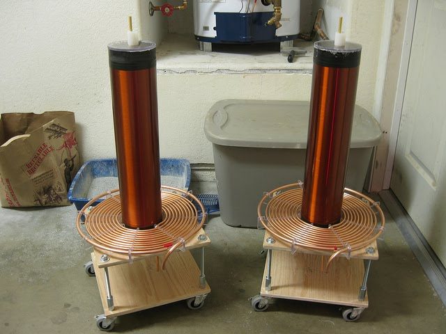
One of the secondary’s was taken from DRSSTC 1 the other secondary had to be made from scratch. The base section and primaries’ were also made new for both coils. I already had one of the 18 x 4.5 toroids on hand, the other toroid had to be ordered for the second coil. The base of the coil includes casters for easy transport and positioning of the coils.
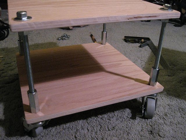
The base of each coil was made from oak ply wood sheet separated by 3/8 threaded rod. Normally in a DRSSTC it would be bad to have steel rod so close to the primary as the steel would heat up and could possibly start a fire but in this design the current in the primary was low enough that it didn’t cause heating of the steel rod.
H Bridge and MMC
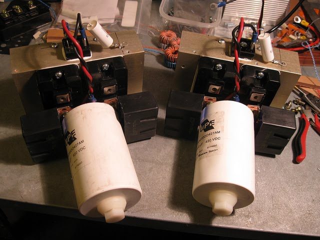
The H bridge used in these coils was built using two CM300DY-12H half bridge modules per coil. These IGBTs proved to be very reliable at 700Apk. The bridge doesn’t usually get above room-temp during normal operation. The bridge also uses a RIFA 2700uF 480VDC Inverter grade DC link capacitor. These are very rugged caps that can supply large amounts of pulsed current on a burst by burst basis. The bus structure was also designed to be very low inductance to help eliminate stress on the switches. 2uF 1000V IGBT snubbing capacitors were also placed across the IGBT terminals to absorb and transient voltages that may appear during a switching transition.
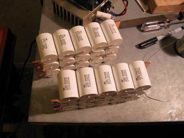
The MMC was also a part what was overbuilt to meet a high reliability standard of the rest of the coil. The MMC is rated to about 900Apk as per datasheet spec but the MMC is usually only run at no more than 700Apk during normal operation. MMC was also constructed with heavy duty 1/8 inch thick copper bus bar and put in a air cooled polycarbonate case.
Controller and final assembly
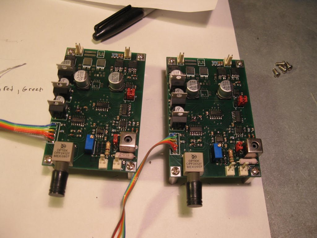
The controller used was Steve Ward’s UD 2.0; this controller was used mainly for its ability to switch the large IGBT bricks before the zero crossing in the primary circuit. The controller uses a gate drive transformer to drive the IGBT H bridge.
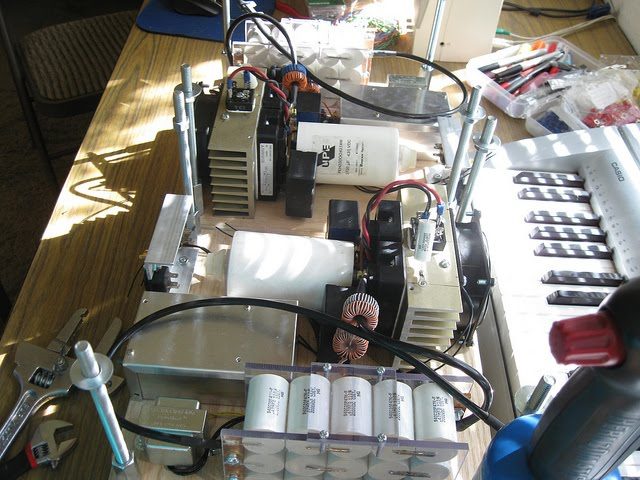
Final assembly was about the easiest part of the whole build. All of the sub systems such as the H bridges, MMC s and controllers were mounted on the bottom level of the Tesla Coil base. The primary secondary and topload were all mounted to the top section of the Tesla coil base. The sub systems were then wire together for final operation.
Running and testing
These coil have now give close to 2 year of reliable service, about 100 hours of continuous running. They have been taking to many shows and events and never failed to impress the audience with there musical capability. This system is by far the most reliably one I have built to date and I’m sure it will continue to do so for many years into the future.